May 3, 2026
Breakthrough
Cost-Engineered Gearbox Supports — Industrial Hardware Repurposed
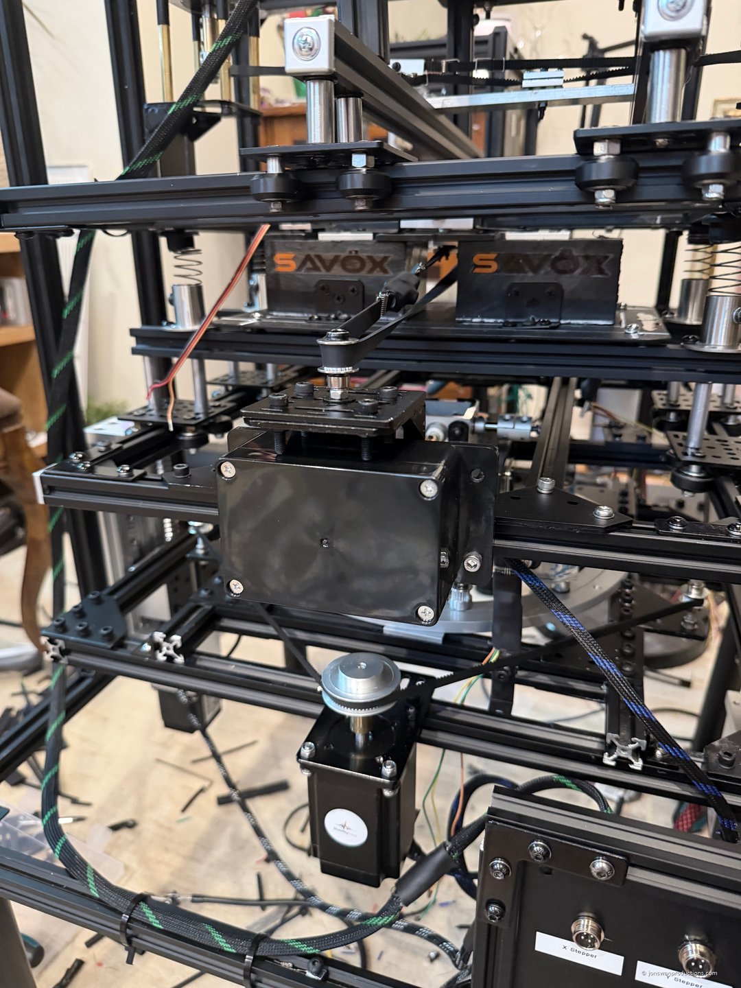
Sometimes the right answer is hiding in another aisle. Two hours of physical search at the hardware store revealed that 3/8" steel electrical conduit hangers — rated for sustained pipe loading in commercial buildings — make precision-adjustable supports for the WaveForge gearbox/stepper assembly at roughly 4% of the cost of dedicated commercial gearbox mounts.
The pattern repeats. This is the fourth example of structural utility in mass-market hardware not designed for the purpose:
- Closet rod brackets + spring + rubber plugs → tunable shock absorber assembly
- M5 T-nuts + heat shrink → adjustable Hall sensor mounts
- Romex household wiring + Wago push connectors → code-compliant DC distribution junction
- Electrical conduit hangers + threaded rod → precision gearbox supports (today)
Why this matters for StabilityCore: Every commercial seismic isolation product on the market today is engineered around expensive specialty hardware. By systematically substituting code-rated industrial hardware that is over-built for typical use, we make the entire technology accessible at a fraction of incumbent pricing — viable for university research labs, developing-world deployment, and consumer applications that would never reach commercial seismic isolation budgets.
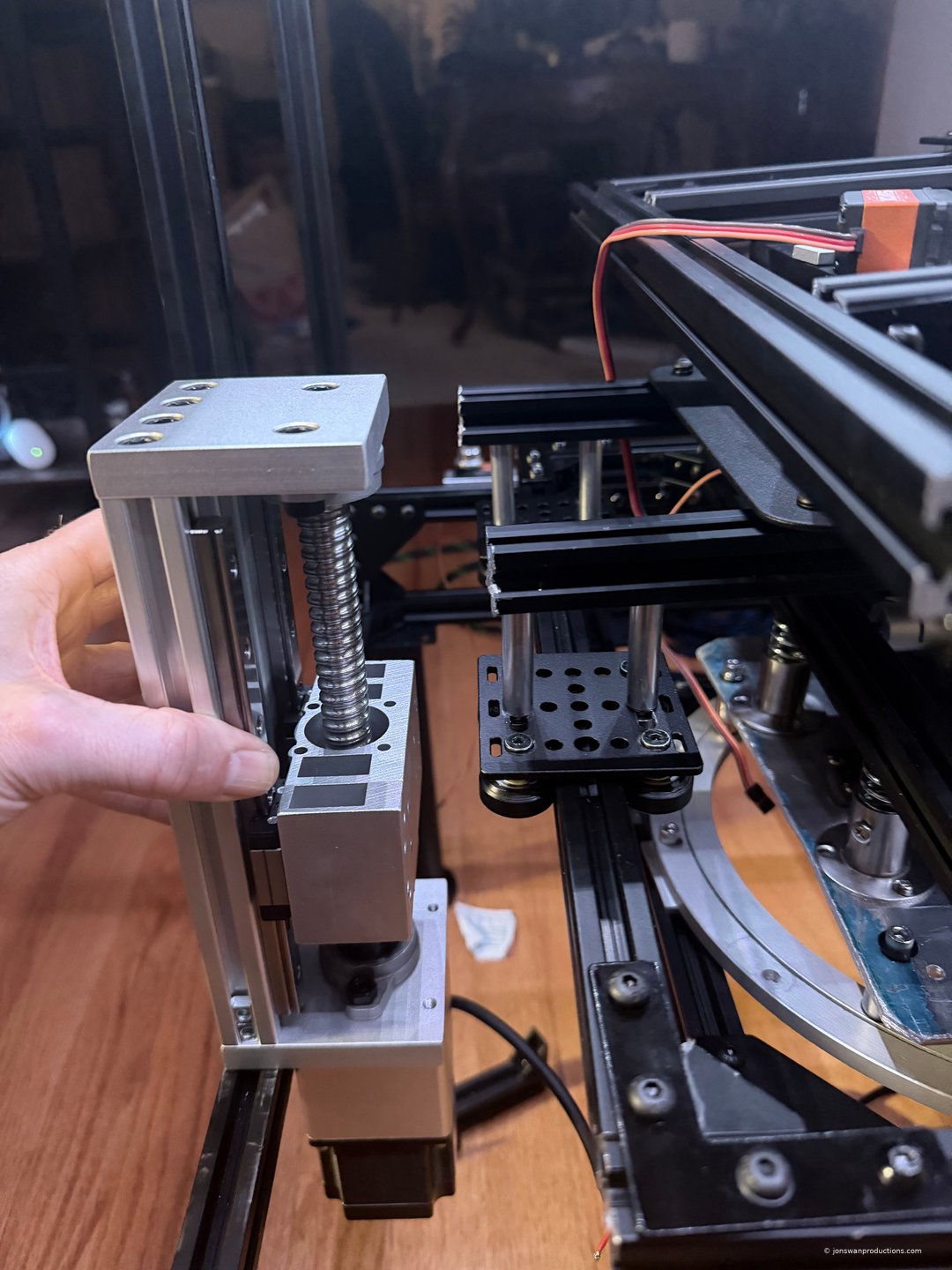
Two-point support architecture: Top flange + bottom bracket anchor both ends of the threaded rod, preventing wobble or moment loading. Slotted holes in the U-bracket give X/Y horizontal adjustment. Threaded rod gives sub-millimeter vertical alignment. Rubber bushing breaks the vibration path between gearbox and drivetrain — quieter operation, longer bearing life, cleaner sensor readings.
$80 of capability for $6 in hardware. Not because we cut corners — because the right hardware was hiding in the electrical aisle.
May 2, 2026
Milestone
Driver Power Layer Complete — Professional Termination Throughout
The DC distribution layer is finished to industrial spec. Every stepper driver power terminal is now connected with hex-crimped ferrules. Every wire is color-coded silicone stranded with nylon braided sleeve and heat-shrink strain relief. Every connection has been tug-tested. The shake table now has the kind of wiring that production motor controllers ship with.
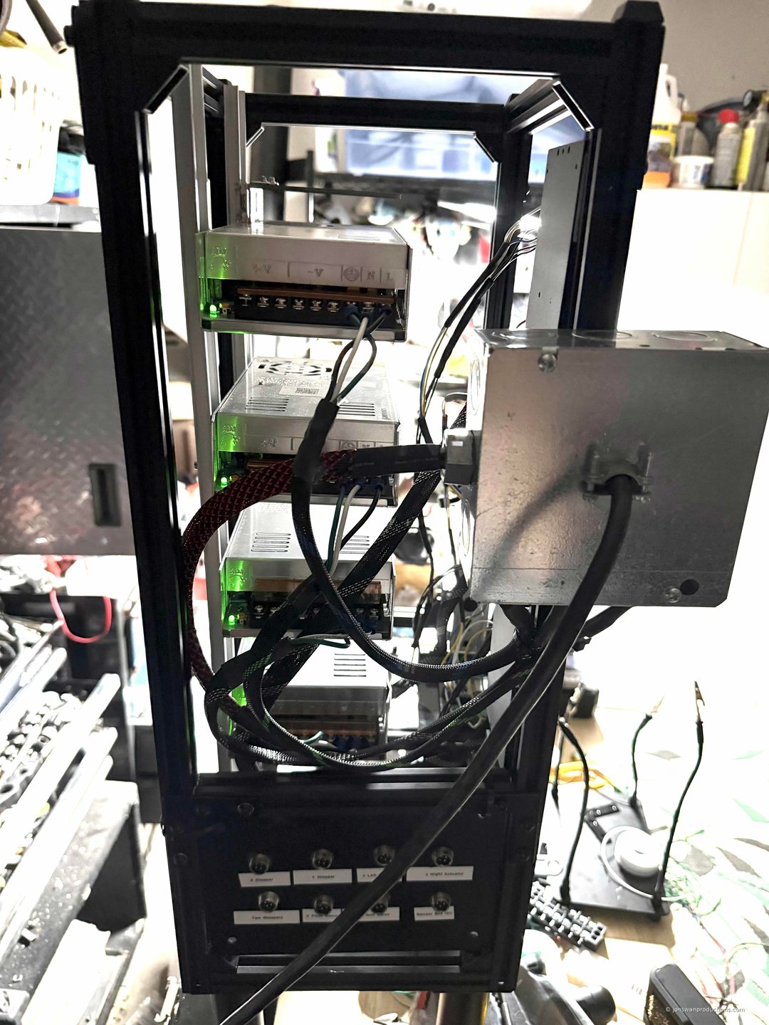
All 4 power supplies energized after final AC junction box wiring. Code-compliant Romex feed, Wago push-connector distribution, stranded silicone branch wiring with ferrules at every termination. Each PSU’s green LED is its own milestone.
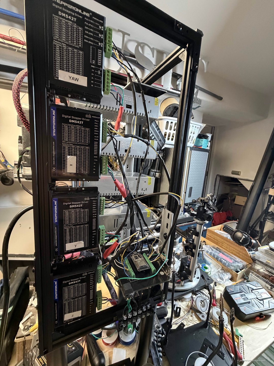
The completed power tower. AC junction box at top (mounted to outer 2020 rail), four 36V PSUs in the rack, four DM542T stepper drivers stacked vertically, XL4016 buck converter dialed to 6.4V for the servo rail, and the GX12 patch bay at the bottom. 32 individual wires consolidated into 8 modular cable ports.
Termination upgrade with the new ferrule kit: A 1900-piece hex-crimping ferrule kit was validated as essential equipment. Every previously-soldered terminal was re-terminated with proper crimped ferrules — eliminating cold-flow risk, providing gas-tight electrical contact, and producing visually consistent termination quality across the rack. The retrofit took under two hours and closed a long-term reliability concern flagged earlier in the build.
Servo rail commissioned: XL4016 buck converter mounted on standoffs (open-air for thermal dissipation), dialed to 6.4V output to compensate for GX12 contact resistance and 4-foot tether wire drop. Voltage verified at the far end of the tether matches the buck output. Y Roll Servo wired through the full tower patch bay → tether → table patch bay path. Pitch servo wiring planned next session.
Three-layer cable protection on every interconnect:
- Inner: stranded silicone wire (flexible, vibration-tolerant, 200°C jacket)
- Middle: nylon braided sleeve (abrasion protection, professional finish)
- Outer/junction: heat shrink at terminations (strain relief at the highest-stress point)
The next phase: Hall sensor installation (Z1, Z2, Yaw) once replacement parts arrive, then first power-on verification, then ESP32 firmware flash and motor commissioning. Calibration will use the gravity-drop sequence (designed earlier) to register the Z actuators against the level hard stops, then home each sensor independently.
The boring quality work is what makes future demos possible. Every connection on this rack will outlast the rest of the build.
April 27, 2026
Breakthrough
G-Lab Infrastructure Day — Three Maker Inventions in One Session
Five hours of grunt work yielded three transferable engineering techniques. The G-Lab (the garage R&D workspace) saw a major infrastructure push that produced the patch bay system, the closet rod bracket shock absorber, and the gravity-drop calibration method — all of which will outlive this prototype and apply to future builds.
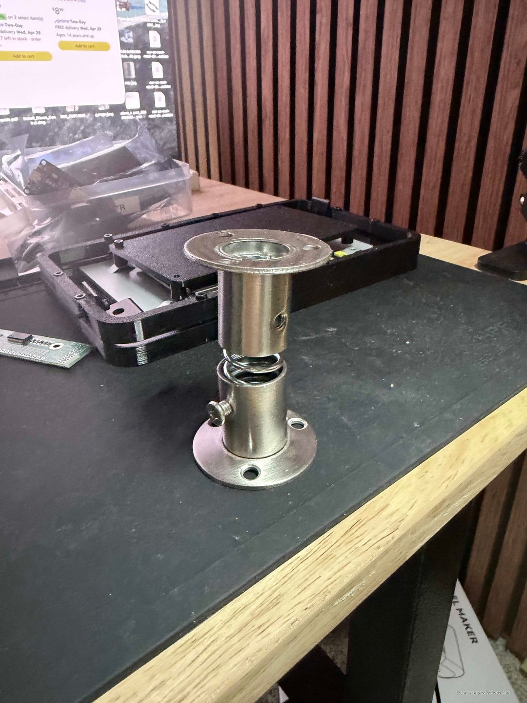
The closet rod bracket + spring + rubber plug shock absorber. $9 in hardware-store components delivers what a $80–$300 commercial spring isolator does. The bracket’s tube structure constrains the spring laterally; the integral flange provides mounting; rubber plugs at top and bottom add damping and replace any need for set-screw pre-load adjustment. Stainless steel finish makes it look intentional.
Z axis actuator. Two of these drive the platform up and down in parallel from the same ESP32 control pins, with shock absorbers at the corners handling mechanical load sharing. The MPU6050 IMU on the platform provides closed-loop tilt feedback for any sync drift between actuators.
X axis counterweight — an ABS box filled with BBs. Custom mass tuning for axis balance, exact weight set by how full you fill it. Same logic as a calibration weight set, built from $10 of materials.
Three maker techniques saved (each worth its own future patent claim):
- Closet rod brackets + spring + rubber plug → $9–30 shock absorber assembly that replaces $80–300 commercial spring isolators. Tunable damping. Reusable hardware. Can be specified into university kits for replication.
- Gravity-drop calibration to level hard stops → zero-sensor Z-axis registration using kinematic referencing. Disable Z motors → gravity drops both actuators to physically level hard stops → re-enable motors → both actuators are now synchronized at the same physical zero. The hard stops are the reference. No measurement step required.
- MPU verification layer → the IMU on the platform validates that the gravity drop actually produced level. Triple-redundant calibration: gravity zero + Hall sensor home + MPU verification. Any single layer can fail and the others detect it.
Patch bay architecture: 8 GX12 aviation connectors mounted to the outer 2020 rail of the power tower as a single integrated unit. 32 individual wires consolidated into 8 modular cable ports. Each port labeled (X Stepper / Y Stepper / Z Left Actuator / Z Right Actuator / Yaw Stepper / X Pitch Servo / Y Roll Servo / Sensor Bus I2C). The shake table can be fully disconnected from the power tower as one operation — ready for transport, service, or future V2 swap.
Z architecture decision: Two Z actuators driven in parallel from the same ESP32 control pins (GPIO 18/19/23) for synchronization. Spring shock absorbers at the corners handle any mechanical mismatch. MPU6050 closed-loop tilt feedback corrects for drift in real time. Spare ports reserved for future independent Z2 control if needed.
Lab feels like a real working space now. Played jazz on the JBL while soldering. Three inventions came out of one day’s grunt work — all three will be replicated in future builds and may end up in patent claims.
May 3, 2026
Operations
G-Lab Reaches Operational Maturity — Workspace as Force Multiplier
The build outgrew the original workspace. As StabilityCore and WaveForge prototyping advanced, the bench area filled up — tools competing with parts competing with the actual builds. The solution was to convert the garage into a dedicated R&D workspace: the G-Lab. Dedicated tool storage, dual workbenches with hardwood tops, organized parts inventory, and the kind of physical infrastructure that compounds productivity on every future session.
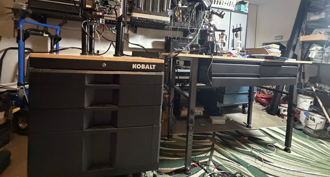
The G-Lab. Kobalt 4-drawer rolling cabinet with hardwood top (left, picked up from a Lowes display unit at ~50% off retail) paired with an adjustable-height rolling workbench (right). Dual hardwood surfaces, mobile via casters, expandable as the build needs grow. Power tower, drivers, and patch bay visible in the background.
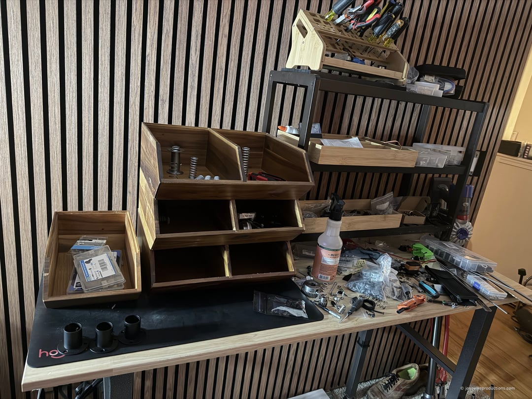
Wooden parts bins in the upstairs office. Naturally anti-static (won’t damage sensitive components like ESP32s, Hall sensors, or IMUs through static discharge). Open-front design speeds part retrieval. Eventually getting these synced to a digital inventory program for true parts management.
What recent infrastructure adds:
- 4-drawer rolling Kobalt cabinet with hardwood top (added 2026-05-02 from a Lowes display unit, ~50% off retail) — doubles bench surface and adds 4 dedicated drawers for tool/parts organization
- Adjustable-height rolling workbench — secondary surface for staging, layout, and detail work
- 1900-piece hex ferrule crimper kit covering AWG 23–10 — standardized termination quality across every connection in the build
- Wooden anti-static parts bins for fine electronics in the upstairs office (separate clean-work zone from the dirty/heavy garage work)
- Brother label printer for connector and drawer labels — small detail, big professional polish
- Bamboo tool holders, multimeters, soldering iron, heat gun all permanently staged
Two-floor lab architecture mirrors how serious R&D operations are organized: dirty/heavy work in the G-Lab (garage), fine assembly and electronics in the upstairs office. Different materials, different workflow, different cognitive modes. Switching between them through the day is restorative — the rest period for one is the work period for the other.
Each upgrade compounds the productivity of every future session. The lab isn’t just where work happens — the lab is part of how the work gets done well.
April 23, 2026
Strategic Pivot
From "Earthquake Simulator" to "Wave Simulator" — Unifying the Product Line
Waves are waves. Whether they travel through earth (seismic), water (ocean), air (wind), or light, every wave in nature follows the same fundamental physics — frequency, amplitude, phase, direction, propagation. The 6-DOF platform we built doesn’t just simulate earthquakes. It simulates every form of wave motion. Today we’re officially repositioning it as a Wave Simulator.
Why this matters:
- Cross-company platform — The same device tests StabilityCore earthquake isolation AND WaveForge ocean energy. One R&D investment, two commercial product lines.
- Expanded market — Seismic engineering, marine energy, aerospace vibration, automotive testing, packaging durability, entertainment motion simulators — all are potential customers.
- Unified grant eligibility — Eligible for DOE earthquake engineering grants AND DOE Water Power grants AND potentially aerospace/defense funding.
- Stronger IP positioning — The existing provisional patent (#64/021,085) already covers the hardware broadly. This is a marketing/positioning shift, not a patent rewrite.
- Consistent with the unified wave theory that runs through all our work — harvest the wave, don’t fight it. That applies whether the wave is seismic, oceanic, acoustic, or electromagnetic.
The hardware is identical. What changes is the story: “We built a programmable 6-DOF wave simulator. It can play back any wave form in nature — from a Magnitude 8 earthquake to a Pacific storm surge to the vibration profile of a Mars rover landing. One machine, every wave phenomenon.”
Going forward, the device is a Wave Simulator. The company behind it (StabilityCore) specializes in its seismic applications and active isolation technology. Sister company WaveForge uses it for ocean energy validation. Future customers will use it for whatever waves they need to study. One platform, unlimited applications.
April 23, 2026
Breakthrough
WaveForge OIMH Gearbox Upgrade — 5:1 Speed Increase Incoming
Major amplification upgrade arriving. A STEPPERONLINE Planetary Gearbox (Gear Ratio 5:1, Backlash 15 arc-min, 10mm Shaft, NEMA 23) is now installed on the WaveForge OIMH test assembly, set to quintuple the generator output speed.
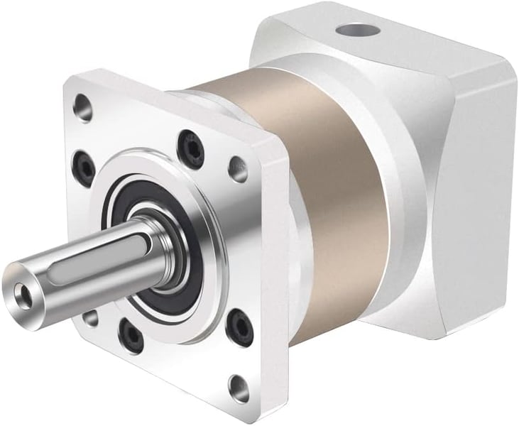
STEPPERONLINE 5:1 planetary gearbox — precision machined, 15 arc-min backlash, NEMA 23 flange mount, 10mm output shaft.
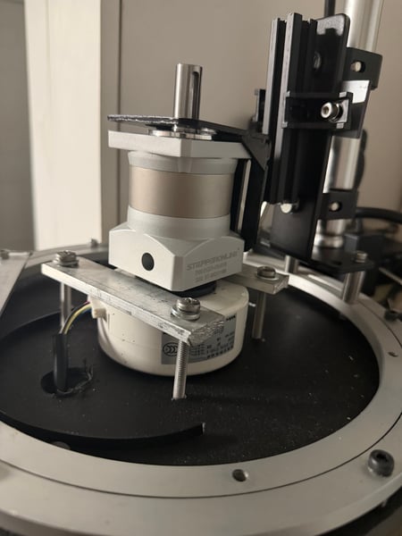
Gearbox staged for installation on the WaveForge OIMH test assembly. Ready to multiply orbital speed into dramatically higher voltage output.
What changes with 5:1 gearing:
- Gentle rocking (previously 3V) → projected ~14V output — enough to light the demo LED panels from minimal input
- Realistic swell (previously 4V) → projected ~18V output
- Active seas (previously 8V) → projected ~35V output
- Storm conditions (previously 13V) → projected ~58V output
Why a gearbox instead of pulleys: After hours of troubleshooting belt-and-pulley mechanical issues — bore sizing, bearing requirements, alignment, tension — the gearbox approach delivers the same amplification with dramatically cleaner integration. One sealed, lubricated unit with precise tolerances replaces a fragile belt drive. This is the right answer for production buoys anyway, so the bench demo gets the same upgrade.
Installation details:
- Part: STEPPERONLINE Planetary Gearbox — Gear Ratio 5:1, Backlash 15 arc-min, 10mm Shaft, for NEMA 23 Stepper Motor
- Fits a spare NEMA 23 mounting bracket already on hand
- 10mm output shaft with matched couplers arriving tomorrow
- Replaces the crank arm that previously drove the generator at 1:1 ratio
Scaling implications: At 25× linear scale (50-foot production buoy), 5:1 gearing combined with the fourth-power scaling law translates to tens of megawatts per buoy in active sea conditions. Combined with the bicycle-style derailleur concept for variable gearing under different sea states, WaveForge adapts to any wave conditions automatically.
Next: Couplers arrive tomorrow. Install, align, test. First measured voltage with 5:1 amplification will be documented in a follow-up post. Expecting LED panels to light up with minimal hand-rocking — the kind of demo that makes the physics undeniable.
The gearbox is an off-the-shelf industrial component. The innovation is integrating it with the omnidirectional OIMH and adjustable orbital radius to create a system that scales from bench demo to multi-megawatt grid production using the same fundamental architecture.
April 23, 2026
Milestone
Control Console Wiring Complete — 14 Buttons Live on I2C
Major wiring milestone. The wave simulator control console is now fully wired for input. All 14 illuminated push buttons are soldered, heat-shrunk, and successfully communicating with the ESP32 through an MCP23017 I/O expander on the I2C bus.
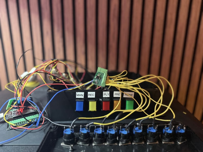
Control console interior — 14 push buttons wired through MCP23017 I/O expander. Yellow wires = button signals, red/blue = LED power rails, all soldered with heat-shrink strain relief. Wiring will route cleanly behind the front panel once the box is closed up.
What was built today:
- 14 push buttons soldered to yellow signal wires with heat-shrink tubing on every joint
- MCP23017 I/O expander wired to ESP32 via I2C (only 2 GPIO pins instead of 14)
- Per-button debouncing implemented in firmware — 50ms stability window, non-blocking state machine
- Ground bus bar distribution — all 14 button commons plus LED grounds to a shared brass bus
- All 14 buttons tested and confirmed operational in Serial Monitor
Console layout:
- 9 round buttons (top strip): RDY, RUN, FLT status indicators + X, Y, Z, YAW, PITCH, ROLL axis enables
- 5 square buttons (bottom strip): MANUAL, RECORD, PLAYBACK, PRESET, HOME mode selection
- 5 potentiometers for live PID gain tuning — previously validated
- 1.48” ESP32-S3 Touch LCD for menu navigation and real-time status
- E-stop mushroom button on the side for safety
Why MCP23017: Expanding 14 button inputs + 14 LED outputs to just 2 ESP32 pins via I2C. Frees up GPIO for other sensors and keeps the wiring manageable. The chip detected instantly at address 0x20 on first power-up — clean wiring paid off.
Next phase: Wire the second MCP23017 (address 0x21) for the 14 button LEDs. Then the console becomes bidirectional — press a button to trigger a mode, the corresponding LED lights up as feedback.
Methodical one-step-at-a-time approach. 14 buttons, 14 clean solder joints, 14 heat-shrunk terminations. No shortcuts. Professional-grade interior under what will be a clean front panel.
April 5, 2026
Milestone
Mechanical Assembly Complete — 6-DOF Shake Table Ready for Electronics
The mechanical phase is done. After weeks of precision fabrication, hundreds of screws, cuts, bruises, and late nights — the StabilityCore 6-degree-of-freedom shake table is mechanically complete and ready for electronics and firmware.
What’s built:
- X-axis translation — NEMA 23 stepper on linear rails with GT2 belt drive and idler wheels for maximum grip
- Y-axis translation — duplicate of X-axis, rotated 90°
- Z-axis vertical — two ball-screw linear actuators in diagonal opposite positions, connected by 2020 lifting frame
- Yaw rotation — NEMA 23 stepper driving aluminum lazy susan via belt and idlers, ±30° with mechanical stops
- X-axis pitch — Savox servo with bevel gear assembly, precision brass couplers, red Loctite on all joints
- Y-axis pitch — Savox servo with identical bevel gear assembly
Passive isolation system:
- Multi-layer spring isolation with matched rates per level — stiffer springs at bottom, softer at top
- Rubber stoppers at spring limits secured with M5 screws through 2020 T-nuts
- Extension springs with ball-bearing fishing swivels for Z-axis counterbalance — free rotation in all directions
- Cast iron payload plate on 2020 spacers with pulley clearance underneath
Professional wiring infrastructure:
- GX12 4-pin aviation connectors for all motor connections
- Color-coded nylon cable sleeves with heat-shrink terminations
- Patch bay on both electronics rack and shake table frame
- Fully disconnectable for transport — unplug 8 connectors and the table separates from the rack
Next phase: Electronics — connecting stepper drivers, wiring the GX12 patch bay, mounting ESP32 boards, sensor installation, and firmware development. Then PID tuning on all 6 axes and historical earthquake waveform playback.
80+ hours of build time. One person. Every screw, every bracket, every alignment decision. The mechanical foundation is solid. Now the machine learns to move on its own.
April 4, 2026
Breakthrough
WaveForge OIMH First Voltage — Wave Energy Validated on the Shake Table
Historic day. First measured voltage from the Orbital Inertial Mass Harvester (OIMH) — WaveForge’s wave energy prototype tested on the StabilityCore shake table platform.
Measured DC voltage data:
- Gentle tilt rocking (~1 RPM): 3V
- Realistic ocean swell (30 BPM): 4V
- Moderate swell (40 BPM): 5–6V
- Active seas (60 BPM): 8V
- Storm conditions (100 BPM): 13V
Key discovery: the offset eccentric mass automatically converts linear rocking into circular orbital motion without any perpendicular nudge input. Pure physics — the asymmetric gravitational pull on the off-center weight self-converts the motion. This confirms the “resonant orbital pumping” mode documented in the WaveForge technical paper.
Two patented technologies validating each other on one platform: StabilityCore simulates the ocean, WaveForge harvests the energy. The shake table isn’t just a seismic simulator — it’s a wave energy research platform.
March 30, 2026
Milestone
Shake Table Provisional Patent Filed
Filed provisional patent for the shake table itself as a standalone research instrument.
- Application #64/021,085 — 28 claims
- Covers: 6-DOF platform, distributed ESP32 PID control, spring isolation architecture, volumetric laser visualization, historical earthquake playback, physical fader tuning, solar-powered portable operation, science kit educational deployment
- Filing fee: $130 (small entity)
This is the second StabilityCore patent (the first covers the full-scale building isolation system, #63/986,480). The shake table patent protects the bench-scale instrument that validates the technology and generates revenue through science kit sales.
Total StabilityCore IP portfolio: 2 provisional patents, 102 combined claims.
March 16–28, 2026
Build Phase
Intensive Mechanical Build — From Frame to Nearly Complete
Two weeks of intensive daily build sessions transforming the 2020 aluminum extrusion frame into a precision 6-DOF motion platform:
- March 16: Outer frame nylon nut/washer upgrade, sensor architecture planning
- March 17: Registered 3 LLCs (WaveForge, StabilityCore, DayLux), filed WaveForge provisional patent
- March 21: Y-axis 80% complete, Z-axis progress, Govee lighting installed
- March 22: Continued Y-axis assembly, Z-axis mounting
- March 24: Spacers installed, GX12 patch bay ordered, bird app security hardened
- March 25: Y-axis springs installed, X-axis pulleys tensioned, all axes smooth
- March 26: Frame alignment, cable sleeves started
- March 27: Cast iron payload plate installed, inner frame in outer frame complete
- March 28: Top layer complete, weaker springs on Y-axis, Savox servos arrived
Lessons learned: manufactured holes can’t be trusted for precision alignment — always measure. Lock washers + nylon nuts + red Loctite on every critical joint. Spring rates must be matched to actual load at each level. Patience is the most important tool in the box.
February 23, 2026
Breakthrough
Hybrid Magnetic Bearing & Maritime Expansion
Major conceptual breakthrough today. We solved the biggest objection to electromagnetic seismic isolation at building scale: power consumption.
The solution: a hybrid bearing with permanent magnets carrying the static building load (zero power, always on) and electromagnets handling only the dynamic PID trim. The permanent magnets do 95%+ of the heavy lifting — literally. The electromagnets barely have to work.
Added a mu-metal shielding layer between the two magnetic sources to prevent field crosstalk — the same principle used in audio transformers and MRI machines. This enables independent tuning of each layer.
Five-layer bearing stack finalized:
- Permanent magnet half-sphere (passive lift)
- Mu-metal shielding (field isolation)
- Electromagnet (active PID trim)
- Non-magnetic cable tethers (safety limits)
- VFML gas bearing (backup)
Also opened up an entirely new market: maritime stabilization. Same technology, continuous operation. The tagline: "Perfect sleep in stormy seas." Envisioning a full deck of cruise ship sleeping quarters floating on magnetic bearings, plus individual bed isolation.
Conceived a feedforward sensor system using LiDAR, sonar, and machine vision to detect incoming waves and pre-calculate PID corrections before impact. Ships already carry most of this equipment.
Planned a maritime prototype demo: glass of wine on a kayak on the Willamette River, friend drives a waterski boat past, wake hits — wine doesn't move. Two kayaks side by side for comparison. That's the shot.
Finally, wrote the ESP32 stepper motor test sketch for tomorrow's bench test. First real motor spin of the project.
Photos/video coming — stepper test footage tomorrow
February 22–23, 2026
Hardware
Levitation Demo, VFML Pneumatics, and Parts Flood
Shot the hero photo and video of the electromagnetic levitation demo — stainless steel dome floating over the coil base with blue LED underglow. Dark background, clean composition. This is our first real piece of investor-ready content.
Electromagnetic levitation demo — PID-controlled dome floating with zero contact. Same principle at building scale.
Sourced and ordered the complete VFML pneumatic kit (~$82): Schrader fill valve, 12V solenoid dump valve, glycerin pressure gauge, brass manifold tee, push-to-connect fittings, PU tubing, and PTFE tape. All 1/4" NPT threading for compatibility. Also ordered an AIRBANK electric bike pump for clean, button-press pressurization during demos.
Parts are flooding in: load cells, new ESP32s, ball head joints, microSD card, anti-static bags for ESD-safe storage. The workbench is getting crowded.
Designed and ordered SG90 micro servo winch spools in OpenSCAD for the Space Needle prototype cable system. Press-fit onto SG90 spline shaft, 3 guide grooves, line anchor hole.
Add: Parts arrival photos, workbench layout
Earlier Entries
February 22, 2026
Setback
Design Pivot
Servo Speed Problem & Shake Table Redesign
Setback: Bench-tested the Miuzei 20kg servos for PID correction — way too slow. At 0.16 seconds per 60 degrees, they can't track earthquake frequencies. The HS-422 was responsive but still not fast enough for dynamic loads with momentum.
After researching servo specs and calculating momentum requirements for a ~2 lb building model, selected Savox SC-1258TG (0.08s/60°, 12kg, titanium gears) at ~$85 each. Four ordered for the corners. Expensive, but this is where speed matters most.
Bigger pivot: Redesigned the entire shake table from relay-driven linear actuators to a CNC-style dual-axis stepper system. Two NEMA 23 steppers on MGN12H linear rails with GT2 belt drive. This gives precise position control for replaying actual seismograph data — not just random shaking, but "this IS the 1994 Northridge earthquake at 1/25 scale."
Designed a two-layer 20"×20" HDPE enclosure: bottom plate ("bedrock") holds steppers and rails, top plate ("ground") rides on carriages. Three-sided box hides all mechanics, open back for ventilation and access. Sandbags inside for mass.
Also verified all Pololu controllers (4× Simple Motor, 2× Jrk 21v3) over USB. The Jrk's built-in PID with GUI tuning might be useful for correction axes later.
Add: Servo comparison test, shake table enclosure sketch
February 22, 2026
Design
OMSI Earthquake Challenge Game
Designed the interactive exhibit for OMSI Science Fair (5,000+ attendees). Two stations: a main control panel with LED push buttons and slide faders, and a kid-facing joystick station with arcade buttons.
The game: Kid grabs joystick, tries to keep a ping pong ball on the shaking platform. Timer counts up. Ball bounces unpredictably. Ball rolls off = game over.
Then you toggle PID on. Hand the joystick back. The computer counteracts everything they throw at it. Ball stays centered no matter how hard they shake. Eyes go wide.
Added a PvP mode: Red joystick = earthquake attacker, Blue joystick = defender trying to stabilize. Then PID takes over and beats both humans. Ordered a matching blue joystick for the defender station.
The pitch: "You just felt how hard it is. Now imagine a whole building. Our computer does this 200 times per second."
Week 1
February 21, 2026
Design
Modular Cartridge System & Retrofit Revolution
Developed the modular spring cartridge concept — "jack in the box." Pre-compressed, self-contained cartridges with two-stage safety release. Ships locked, installs in an hour, deploys on earthquake detection like an airbag.
Key insight: instead of going under the foundation, insert cartridges directly at post-and-beam connection points. Same install process contractors already use for adjustable jacks. Zero behavior change, same tools, same crew.
Built-in analog pressure gauge on each cartridge — zero-power, always-visible load indicator. Combined with internal force sensors, every cartridge becomes a distributed seismograph node.
Rendered 6 STL files for 3D printing prototypes. Ordered from JLC3DP in MJF PA12-HP (structural) and binder-jetting metal (locking pins).
Add: Cartridge 3D render, STL preview
February 19, 2026
Milestone
Patent Filed
USPTO Provisional Patent filed. Application No. 63/986,480. 35 claims, 23 technical figures. $130 filing fee paid. One year to convert to non-provisional (deadline: February 19, 2027).
Title: "Active Seismic Isolation System with Real-Time PID-Controlled Force Cancellation, Electromagnetic Friction Reduction, Multi-Tier Early Warning, and Self-Sustaining Seismic Energy Harvesting."
The patent covers the full technology stack: PID control algorithms, sensor fusion, electromagnetic friction reduction, Zigbee feedforward prediction, energy harvesting, refrigerant cooling, and adaptive gain scheduling.
Also added "Patent Pending" badges to the stabilitycore.io website. It's real now.
February 18, 2026
Design
Website Launch & Technical Paper
Launched stabilitycore.io on Cloudflare Pages. Four pages: Home (investor pitch), Technology (deep dive), About (founder), Contact. Dark theme, red accents, professional.
Wrote a 10-section academic technical paper with equations, experimental design (6 experiments), and scaling analysis. Expanded patent from 12 to 28 claims including compliant pylon interface, 5-layer defense-in-depth, predictive phase cancellation with Zigbee mesh, and electromagnetic bearing friction reduction.
Designed and ordered first 3D printed parts: pendulum bearing dishes in resin + one in SLM stainless steel (~$255). The steel dish will demo the real bearing surface at scale.
February 2026
Breakthrough
The Church Moment — "Stop Fighting the Vertical"
The VFML (Vertical Force Mitigation Layer) concept didn't come from a whiteboard or a textbook. It came in church.
I was sitting in the pew, thinking about the hardest unsolved problem in the system: vertical earthquake forces. Horizontal isolation has elegant solutions — pendulum bearings, cables, PID correction. But vertical is different physics. You can't just let a building swing sideways on a vertical axis.
Then it hit me: stop fighting it. Just let it go.
An office chair gas cylinder. You pull the lever, the chair drops. It doesn't fight your weight — it accepts it and lets you sink. Then it pumps back up slowly. That's the entire VFML concept: pressurized columns that vent during an earthquake, let the building sink a few inches as the energy is absorbed, then slowly re-inflate afterward.
The sinking IS the absorption. Gravity is the restoring force. The earthquake doesn't need to be fought — it needs to be allowed to pass.
I went home and designed the whole system that afternoon. Four pneumatic posts, O-ring sealed sleeves, a solenoid dump valve triggered by accelerometer. Mechanical relief valves as backup — zero electronics required for basic function. The system degrades from smart to dumb, never from working to broken.
Sometimes the best engineering insights come from the quietest moments.
February 17, 2026
Genesis
Day One
StabilityCore began as an idea: what if you could cancel earthquake forces in real time, like a drone flight controller for buildings?
10 hours of independent research and concept development preceded this day. Today we designed the firmware architecture (PID controller, IMU sensor fusion, actuator manager, earthquake waveform generator), planned the 1/25 scale prototype, created the investment pitch, and drafted the first patent claims.
Platform design: 22"×10" clear acrylic, 45 drilled holes, 9 springs, 8 actuators (4 simulation + 4 stabilization), ESP32 with MPU6050 IMU. Side-by-side demo: two platforms, same earthquake, one with PID, one without.
The journey starts here.
Setbacks & Lessons
Ongoing
Setbacks
What Went Wrong (And What We Learned)
- OONO relay modules + ESP32 = incompatible. Relays need 4-6.5V signal; ESP32 outputs 3.3V. Wasted a session troubleshooting. Lesson: Check signal voltage compatibility BEFORE wiring. Fix: Switched to MOSFET trigger modules (3.3V compatible).
- JQML linear actuators too slow for earthquake simulation. High torque, very low speed. Can't oscillate at earthquake frequencies. Lesson: Actuator speed matters more than force for dynamic simulation. Fix: Shelved for VFML/slow-correction roles. Redesigned shake table with NEMA 23 steppers.
- Miuzei 20kg servos too sluggish for PID correction. 0.16s/60° can't track dynamic loads with momentum. Lesson: Bench test before committing to a design. Fix: Upgraded to Savox SC-1258TG (0.08s/60°).
- SG90 spool walls too thin for 3D printing. JLC3DP rejected first design — 1mm flanges would crack in SLA resin. Lesson: Minimum 2mm walls for SLA. Fix: Redesigned with 2mm flanges, 8mm drum, 14mm flange diameter. Accepted with thin-wall warning.
- Arduino Uno brownout from motor current spike. Driving relay + actuator from Arduino caused resets. Lesson: Separate motor power from logic power. Always.
- TAP Plastics didn't have black HDPE in stock. Ordered white instead. Same material, same strength, just not the color we wanted. Lesson: Cosmetic preferences shouldn't hold up progress.
Every setback pushed us toward a better design. The stepper + belt shake table is far superior to the relay + actuator approach we started with. The Savox servos will outperform the Miuzei by 2×. The MOSFET modules are cleaner than relays. Failures are data.